
The buck–boost solves the step-up-or-down problem with four components, but it charges three penalties for it: the output polarity inverts, both the input and output currents are pulsating, and the switch must block \(V_g+V\).
There is a family of single-switch converters that pays those penalties differently. The Ćuk, SEPIC and Zeta converters all share the same ideal conversion ratio as the buck–boost, but each adds a second inductor and a coupling capacitor that carries the energy from input to output. That extra energy-storage element turns them into fourth-order systems — harder to model, but with ripple and polarity behaviour you cannot get from the basic trio.
First draft — design example, not a validated reference board. The numerical values below are analytical starting points. The accompanying LTspice netlists are teaching resources; native simulator execution and hardware measurements are not yet included.
Reading route: the shared idea → three topologies → worked example → choosing → coupled inductors → control → simulation → applications.
1. The shared idea: transfer energy through a capacitor
Inductors and capacitors both store energy in a switching converter. What distinguishes this family is the series coupling capacitor: it carries the energy-transfer current between switching nodes, while two inductors establish different port-current properties.
Follow the switch and diode states before deciding which element supplies a port. The capacitor voltage cannot jump instantaneously, and each inductor current must remain continuous under finite applied voltage. These two facts determine the interval circuits and explain the three arrangements below.
An inductor permanently in series with a port makes that port current continuous in CCM. Ćuk has inductors at both ports; SEPIC has a continuous input current; Zeta has a continuous output current. These arrangements can ease filtering, but capacitor ripple, layout and common-mode paths still determine practical EMI performance.
The price is a fourth state variable. Two inductor currents and two capacitor voltages give a fourth-order system with two resonances that can interact, which makes both the dynamics and the compensator design meaningfully harder than the second-order basics.
The common steady-state result
All three converters have the same ideal CCM conversion-ratio magnitude as the buck–boost:
\[\boxed{\frac{V}{V_g}=\frac{D}{1-D}} \tag{1}\]and in each one the coupling capacitor’s DC voltage follows from a rule worth internalising: the average voltage across any inductor in steady state is zero, so the DC potential of every node an inductor touches is fixed by whatever it connects to. Apply that rule and the capacitor voltages fall out immediately, as shown for each topology below.
2. The three topologies
Ćuk — continuous current at both ports
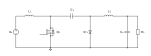
Named after Slobodan Ćuk, this is the buck–boost’s dual. The switch Q pulls node A to ground; the diode D returns current at node B. Because L1 is in series with the input and L2 is in series with the output, neither port has pulsating current — the only topology in this article with that property.
Applying the zero-average-inductor-voltage rule: L1 fixes node A’s average at \(V_g\), and L2 fixes node B’s average at the output \(-V\). So
\[V_{C_s}=V_g+V. \tag{2}\]The coupling capacitor must withstand the sum of input and output voltage — the highest-stressed passive part in the converter. The output is inverted.
SEPIC — continuous input current, non-inverting
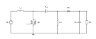
The Single-Ended Primary-Inductor Converter rearranges the same parts so the output is positive. L1 still gives continuous input current, but L2 now sits to ground and the diode feeds the output, so the output current is pulsating exactly as in a boost.
Here L1 fixes node A’s average at \(V_g\) and L2 fixes node B’s average at 0, so
\[V_{C_s}=V_g. \tag{3}\]A lower capacitor stress than the Ćuk, and a non-inverted output — which is why SEPIC is by far the most commonly used of the three.
Zeta — continuous output current, non-inverting
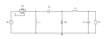
The Zeta is the SEPIC’s mirror image: the switch is now in series with the input (so the input current is pulsating) while L2 is in series with the output (so the output current is continuous). The output is positive.
With L1 fixing node A’s average at 0 and L2 fixing node B’s average at \(V\),
\[V_{C_s}=V \quad\text{(magnitude, for the arrangement drawn above)}. \tag{4}\]Zeta is the least common of the three, largely because it needs a high-side switch, but it is attractive when the load demands low output ripple and the input can tolerate a pulsating draw.
3. A worked example
Take the same specification used across this series so the numbers are directly comparable.
| Quantity | Value |
|---|---|
| Input voltage | 12 V nominal; 8–16 V range |
| Output voltage | 12 V (magnitude) |
| Output power | 30 W → 2.5 A into 4.8 Ω |
| Switching frequency | 100 kHz |
| L1, L2 | 150 µH each |
| Coupling capacitor | 22 µF |
| Duty at nominal | 0.5 |
Inductor currents
Unlike the buck–boost, where one inductor carried 5 A, the current here is split between two inductors:
\[I_{L1}=I_{\mathrm{in}}=\frac{P}{V_g}=2.5\ \mathrm{A}, \qquad I_{L2}=I_o=2.5\ \mathrm{A}. \tag{5}\]Each inductor sees the on-interval voltage \(V_g\) (for the SEPIC, both L1 and \(C_s\)-clamped L2 do), giving the familiar ripple
\[\Delta i_{L}=\frac{V_gD}{Lf_s}=\frac{12\times0.5}{150\ \mu\mathrm{H}\times100\ \mathrm{kHz}}=0.40\ \mathrm{A}. \tag{6}\]The switch still carries \(i_{L1}+i_{L2}\approx5\ \mathrm{A}\) during the on interval, and still blocks \(V_g+V=24\ \mathrm{V}\) — the semiconductor stress is not improved relative to the buck–boost. What improves is the ripple at the ports.
The coupling capacitor
The coupling capacitor is the component beginners under-specify. Its ripple voltage and RMS current are
\[\Delta v_{C_s}\approx\frac{I_oD}{C_sf_s}=\frac{2.5\times0.5}{22\ \mu\mathrm{F}\times100\ \mathrm{kHz}}=0.57\ \mathrm{V}, \tag{7}\] \[I_{C_s,\mathrm{rms}}\approx\sqrt{D\,I_{L2}^2+(1-D)I_{L1}^2}=2.50\ \mathrm{A}. \tag{8}\]2.5 A of RMS ripple current, continuously. This capacitor must be a low-ESR type — ceramic or film — rated for that current at the switching frequency, and it sits at 12 V (SEPIC) or 24 V (Ćuk). A failure here is one of the most common causes of a SEPIC prototype that works on the bench and dies in the field.
The output capacitor: where Ćuk wins
This is the clearest difference between the two inverting-capable options.
In the SEPIC, the diode feeds the output, so the output capacitor absorbs a pulsating current just as in a boost:
\[\Delta v_{o}\approx\frac{I_oD}{C_{\mathrm{out}}f_s}=37.9\ \mathrm{mV}\ \text{at }330\ \mu\mathrm{F}, \qquad I_{C,\mathrm{rms}}\approx I_o\sqrt{\frac{D}{1-D}}=2.5\ \mathrm{A}. \tag{9}\]In the Ćuk, L2 feeds the output continuously, so the capacitor only sees the triangular inductor ripple — the buck-like \(/8\) result:
\[\Delta v_{o}\approx\frac{\Delta i_{L2}}{8C_{\mathrm{out}}f_s}=5.0\ \mathrm{mV}\ \text{at only }100\ \mu\mathrm{F}, \qquad I_{C,\mathrm{rms}}\approx\frac{\Delta i_{L2}}{\sqrt{12}}=0.12\ \mathrm{A}. \tag{10}\]A third of the capacitance gives roughly an eighth of the ripple and about twenty times less capacitor RMS current. That is the Ćuk’s whole argument.
4. Choosing between them
| Buck–boost | Ćuk | SEPIC | Zeta | |
|---|---|---|---|---|
| Ideal gain | \(D/D'\) | \(D/D'\) | \(D/D'\) | \(D/D'\) |
| Output polarity | inverted | inverted | positive | positive |
| Input current | pulsating | continuous | continuous | pulsating |
| Output current | pulsating | continuous | pulsating | continuous |
| Order | 2nd | 4th | 4th | 4th |
| Coupling cap voltage | — | \(V_g+V\) | \(V_g\) | \(V\) |
| Switch referenced to | high side | ground | ground | high side |
| Switch blocking voltage | \(V_g+V\) | \(V_g+V\) | \(V_g+V\) | \(V_g+V\) |
| Components | 4 | 6 | 6 | 6 |
Reading the table as a decision:
- Need a positive output from a ground-referenced switch? SEPIC. This combination is why it dominates in practice — a low-side N-channel MOSFET needs no bootstrap or level shift.
- Need the lowest ripple on both sides and can accept inversion? Ćuk. Ideal for sensitive analogue or RF supplies and for EMI-constrained designs.
- Need a positive output with quiet output current specifically? Zeta, accepting the high-side drive.
- Need the cheapest part count and the ranges barely overlap? Stay with the buck–boost, or use a four-switch non-inverting buck–boost if efficiency matters more than part count.
Note the row that does not improve: every one of these blocks \(V_g+V\) across the switch. None of them fixes the semiconductor stress — they redistribute the ripple, not the voltage.
5. Coupled inductors: a practical shortcut
In both the Ćuk and the SEPIC, L1 and L2 see the same AC voltage waveform across them in steady state. That is not a coincidence — it follows from the coupling capacitor holding a nearly constant DC voltage between the two nodes.
Because the AC voltages match, the two inductors can be wound on a single core as a 1:1 coupled pair. This has three practical consequences:
- One magnetic component instead of two, usually smaller and cheaper than two separate inductors.
- Ripple steering. By deliberately adjusting the leakage inductance, ripple current can be shifted from one winding to the other — and in the limit, nearly cancelled at one port. A Ćuk with a well-designed coupled inductor can achieve remarkably low input ripple.
- Winding polarity is critical. Connect the windings with the wrong phasing and ripple currents add instead of subtracting. This is the single most common mistake when a coupled inductor is first substituted for two discrete parts.
Off-the-shelf coupled inductors are sold specifically for SEPIC and Ćuk service. If you use one, confirm its rated current applies to the sum of both winding currents where relevant, and check saturation at the low-line operating point where \(I_{L1}\) is highest.
6. Dynamics and control
Fourth-order converters are genuinely harder to compensate, and it is worth being honest about why.
Two resonances. The input-side network (\(L_1\) with \(C_s\)) and the output-side network (\(L_2\) with \(C_{\mathrm{out}}\)) each contribute a resonant pair. They are coupled through \(C_s\), so they do not behave as two independent second-order systems. The result is a control-to-output response that can show two lightly damped peaks, sometimes closely spaced.
Right-half-plane zeros. Both the SEPIC and the Ćuk are boost-derived in the sense that raising duty initially steals time from the interval feeding the output, so both carry a right-half-plane zero in CCM. As with the boost and buck–boost, it cannot be cancelled and it caps the achievable bandwidth, and it moves with operating point. The Zeta, whose output is buck-like, is generally reported to be free of an RHP zero in CCM — one of its genuine advantages — but confirm that at your own operating point rather than taking it on trust.
Light damping. With small parasitic resistance, the \(L_1\)–\(C_s\) resonance can be very lightly damped and shows up as sustained ringing after a load step. Many practical designs add a small damping network — a series RC across the coupling capacitor or a resistor in parallel with an inductor — specifically to tame it. Expect to need one.
The practical recommendation for all three is peak current-mode control. The inner current loop damps the dominant resonance, reduces the effective order seen by the voltage loop, and provides cycle-by-cycle protection for a switch that carries \(i_{L1}+i_{L2}\). Voltage-mode control with a Type III compensator is possible but demands accurate knowledge of both resonances and their damping.
For a first design, follow the same discipline used earlier in this series: identify the worst-case corner (lowest input, where duty and inductor current are highest and the RHP zero is lowest), target a crossover well below the minimum RHP-zero frequency, and verify every gain crossing rather than reading a single phase-margin number.
7. Simulate it
Two starter netlists are provided so you can compare the families directly on the same specification:
- sepic_open_loop.cir — non-inverting, 330 µF output capacitor
- cuk_open_loop.cir — inverting, only 100 µF output capacitor
Run both and compare four things:
- Output voltage. SEPIC settles near +12 V, Ćuk near −12 V. Change
DUTYto 0.4 and 0.6 to confirm step-down and step-up from the same circuit. - Output ripple. Measure
Vout_ppon each. The Ćuk should show dramatically less ripple despite having a third of the output capacitance — this is the single most instructive measurement in the article. - Coupling-capacitor voltage.
Vcs_avgshould read about 12 V for the SEPIC and about 24 V for the Ćuk, confirming equations (2) and (3). - Inductor currents.
IL1_avgandIL2_avgshould both read about 2.5 A, confirming that the current is split between two inductors rather than concentrated in one.
Both netlists run to 40 ms before measuring. That is deliberate: these are lightly damped fourth-order circuits and they ring for a long time. If you shorten the run you will measure a value that has not settled — a very common source of confusion when people first simulate a SEPIC.
To see the resonance directly, apply a small step change to the load resistance and watch the ringing on the inductor currents. Then add a series RC damper across \(C_s\) and watch it disappear.
8. Where these converters are used
SEPIC — battery-powered equipment with a wide input. The classic case is a 12 V lead-acid or a multi-cell pack that must produce a regulated 12 V while the source wanders from 9 V to 15 V. The non-inverted output and ground-referenced switch make it the default choice.
SEPIC — LED drivers. Constant-current LED strings where the forward voltage of the string may sit above or below the supply rail across temperature and dimming range.
SEPIC — automotive. The 12 V automotive rail that must survive cold crank and load dump while holding a stable downstream rail; SEPIC competes here with the four-switch buck–boost, trading efficiency for part count.
Ćuk — low-noise and EMI-sensitive supplies. Instrumentation, audio, RF and sensor front ends where continuous current at both ports substantially reduces conducted emissions, and where a negative rail is acceptable or actively wanted.
Ćuk — isolated variants. Splitting the coupling capacitor and inserting a transformer produces an isolated Ćuk, which retains the low-ripple property across the isolation barrier.
Zeta — positive output with a quiet load. Chosen where the load cannot tolerate pulsating current but the polarity must stay positive, and the design can afford a high-side gate drive.
When to avoid all three. If the input never crosses the output, use a buck or a boost. If it does cross and efficiency matters more than part count, a four-switch non-inverting buck–boost will usually beat a SEPIC, because it never blocks \(V_g+V\) and only one leg switches in most of the range. These fourth-order converters earn their place when a single switch, a specific polarity, and low port ripple all matter at once.
That completes the non-isolated family in this series. The next chapters move to isolated topologies — flyback, forward, push–pull and bridge converters, and the LLC resonant converter — where a transformer adds galvanic isolation and a turns ratio to the same underlying volt-second and charge-balance reasoning used throughout.
Further study
Robert W. Erickson and Dragan Maksimović, Fundamentals of Power Electronics, third edition, Springer, 2020. Relevant chapters cover converter synthesis, steady-state analysis of higher-order converters and AC equivalent circuit modelling. The derivations and numerical example here are presented independently; this article is not a reproduction of the textbook.