
Junction temperature is needed in nearly every power-device test, but it is rarely measured by placing a thermometer directly inside the active region. An electrical parameter, infrared image or surface sensor measures a quantity related to temperature. The relationship and its limitations must be established.
This article develops temperature-sensitive electrical parameter (TSEP) measurements as the foundation for thermal resistance, thermal transients and power cycling.
1. Define the temperature being estimated
An operating die is not necessarily isothermal. Current crowding, metallisation and cooling can create local hot spots. A terminal electrical measurement generally provides an effective temperature weighted by the parameter’s physical sensitivity. It should not automatically be identified with the hottest microscopic region.
Case, baseplate, heatsink and coolant temperatures are separate measurements. A thermocouple on a package surface measures that surface, subject to contact and response errors. Infrared measurements require optical access, emissivity correction and sufficient spatial resolution; a package cover hides the die from direct observation.
Define \(T_j\) operationally: for example, the temperature inferred from calibrated diode forward voltage at a specified low sensing current. This definition is part of the result.
2. Choose a parameter that can be calibrated reproducibly
Possible TSEPs include diode forward voltage, on-state resistance, threshold-related quantities and device-specific switching parameters. Their sensitivity can depend on current, gate bias, device technology and bias history. A MOSFET body-diode method does not transfer directly to a GaN device without that junction.
Let the measured electrical quantity be y. At fixed sensing conditions, calibrate
\[y=f(T_j),\qquad T_j=f^{-1}(y). \tag{1}\]Over a verified limited interval, a linear approximation may be sufficient:
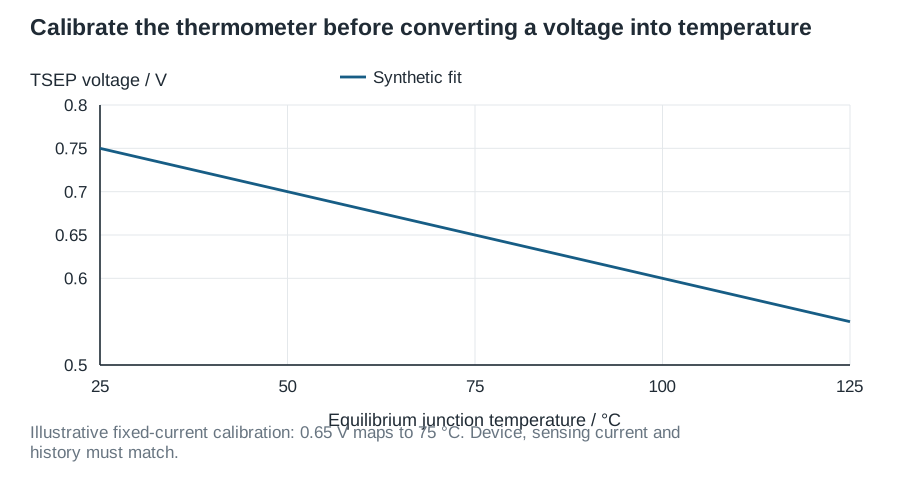
\[y=y_0+k_T(T_j-T_0),\qquad T_j=T_0+\frac{y-y_0}{k_T}. \tag{2}\]Never assume a universal voltage-temperature coefficient. Measure it for the device population and the intended sensing conditions, using an appropriate fit if the response is nonlinear.
3. Carry out a static calibration
Place the unstressed device on a controlled thermal fixture and establish several calibration temperatures spanning the intended range. Allow the die, package and reference sensor to approach equilibrium. Use a sensing current small enough that its self-heating is negligible within the required uncertainty.
At each temperature, record the reference temperature, current, gate condition, sampling delay, terminal voltage and repeated readings. A four-wire connection can separate lead drop from the sensed junction-related voltage. Sweep temperature in both directions if hysteresis or drift is relevant.
Fit the calibration curve, inspect residuals and retain verification points outside the fitting subset. If devices differ materially, use individual calibration rather than treating one coefficient as a batch constant.
An illustrative calibration has \(V_F=0.750\ \mathrm V\) at 25 °C and \(k_T=-2.00\ \mathrm{mV/K}\). A reading of 0.650 V at the same sensing current corresponds to
\[T_j=25+\frac{0.650-0.750}{-0.002}=75\ ^\circ\mathrm C. \tag{3}\]This is a synthetic example, not a material specification.
4. Change from heating to sensing without hiding the transient
During a thermal test, apply a known heating power, then switch to the calibrated sensing condition. Large heating current may prevent simultaneous low-current sensing. Switching the circuit introduces a finite electrical settling time, and the die begins cooling during that time.
If the first trustworthy reading is at delay \(t_d\), it estimates \(T_j(t_d)\), not automatically \(T_j(0^+)\). At the same time, readings taken too early can contain charge-storage, trapping, probe-recovery and switching artefacts.
Record the delay, demonstrate electrical settling with appropriate control experiments and quantify how much cooling can occur before sensing. Extrapolation to switch-off can be useful, but its selected time interval and thermal assumptions must be stated. A fitted early-time curve is not direct evidence of an unobserved hot spot.
If a linear model applies and heating was held to steady state, the temperature drop during the blind interval is related to the heating step response:
\[T_j(0^+)-T_j(t_d)=P_HZ_{\mathrm{th}}(t_d). \tag{4}\]Finite heating duration requires a different expression, derived in the transient chapter. This relation also explains why a sensing delay acceptable for one package may be unacceptable for a faster thermal structure.
5. Separate temperature sensitivity from state sensitivity
A parameter may change because of temperature, trapping, contact resistance or permanent degradation. Dynamic on-resistance after blocking stress, for example, is not a temperature-only signal. Using it as an unqualified thermometer can interpret charge trapping as self-heating.
Specify the full preconditioning history and sensing time. Compare a heated device with an electrically stressed device held at a known temperature. Recheck calibration after ageing when the selected parameter is itself a degradation indicator. Otherwise a drifting thermometer can distort the apparent ageing rate.
6. Carry uncertainty through the inversion
For the linear calibration, an approximate uncertainty expression, omitting covariance terms, is
\[u_T^2\approx u_{T_0}^2+ \frac{u_y^2+u_{y_0}^2}{k_T^2}+ \frac{(y-y_0)^2}{k_T^4}u_{k_T}^2. \tag{5}\]Here u denotes standard uncertainty, not maximum error. Calibration fit parameters are often correlated; include that covariance in a complete budget. Reference-sensor placement, thermal gradients, sensing-current accuracy and delay correction add further contributions.
At a sensitivity magnitude of 2 mV/K, 1 mV of voltage uncertainty alone corresponds to 0.5 K. Additional digits on a voltmeter do not remove calibration or physical-model errors.
7. Validate what the measurement can support
Compare calibrated electrical temperature with an independent accessible temperature reference under equilibrium conditions. Check repeated heating/cooling runs and confirm that changing sensing current within the validated range does not alter the inferred temperature unexpectedly. For modules, investigate whether multiple dies contribute unequally to the terminal signal.
Preserve the raw calibration data and the timing diagram with every thermal record. Siemens’ thermal-testing overview describes electrical thermal-transient measurements as an established method; the accuracy of a particular test still depends on its calibration, fixture and boundary conditions.