
A switching test describes ordinary operation under specified conditions. A robustness test asks how a device behaves during a defined abnormal event. These are different experiments: surviving a double pulse does not establish avalanche capability, and surviving one short circuit does not establish repetitive-fault life.
This chapter explains the quantities and evidence needed to evaluate such events. Test execution requires a device-specific procedure, rated containment and protection. It does not prescribe a fault pulse for an unspecified semiconductor. Return to the characterisation guide for the complete test map.
1. Read safe operating area as a conditional boundary
Safe operating area (SOA) relates allowed combinations of voltage, current and time under stated starting temperature and mounting conditions. Continuous current, pulsed current and voltage ratings cannot be combined independently to construct a permissible operating point.
For a constant-power pulse and an applicable thermal model,
\[\Delta T_j(t_p)=PZ_{\mathrm{th}}(t_p). \tag{1}\]This estimates average thermal rise. It does not capture every local current-concentration, electrothermal instability or gate-related limit. Linear-mode SOA, reverse-bias SOA for relevant bipolar devices and short-circuit capability describe different conditions. Use the selected device’s documented boundaries and terminology.
Record the full voltage-current trajectory, not only its peak current. Also record pulse duration, repetition, initial temperature and the mechanism that terminates the event.
2. Understand unclamped inductive switching
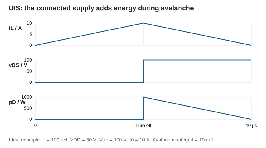
In an unclamped inductive switching (UIS) test, an inductor is first energised through the device. When the device turns off, the inductive current requires a path. For an avalanche-capable MOSFET in the specified fixture, its drain voltage can rise into avalanche and the current decays while energy is dissipated.
The initially stored magnetic energy is
\[E_L=\frac12LI_0^2. \tag{2}\]It is not always equal to DUT avalanche energy. In a simplified circuit where a supply \(V_{DD}\) remains connected and avalanche voltage \(V_{AV}\) is constant,
\[\frac{di}{dt}=-\frac{V_{AV}-V_{DD}}{L},\qquad t_{AV}=\frac{LI_0}{V_{AV}-V_{DD}}, \tag{3}\] \[E_{AV}=\int_0^{t_{AV}}V_{AV}i(t)\,dt =\frac12LI_0^2\frac{V_{AV}}{V_{AV}-V_{DD}}. \tag{4}\]The supply contributes energy during decay. If the source is appropriately decoupled from that interval, the ideal result reduces to the stored inductive energy. Actual waveforms, voltage dependence and other dissipation paths require direct integration. Infineon’s avalanche design guidelines distinguish the fixture arrangements and their energy accounting.
As an illustrative calculation, 100 µH carrying 10 A stores 5 mJ. With a connected 50 V source and a constant 100 V avalanche plateau, the simplified DUT energy is 10 mJ. These values illustrate the accounting; they are not recommended test conditions.
Do not assume that a GaN device or an unqualified device has the avalanche behaviour of a rated silicon MOSFET. Device technology and manufacturer limits determine whether this is an appropriate test at all.
3. Define a short-circuit event precisely
A short present before turn-on and a fault arising during conduction create different electrical and thermal trajectories. Relevant conditions include bus voltage, gate bias, source inductance, initial junction temperature, fault-loop impedance and turn-off behaviour.
Measure fault energy as
\[E_{SC}=\int_{t_0}^{t_1}v_D(t)i_D(t)\,dt. \tag{5}\]A rectangular approximation \(V_DI_Dt_p\) is only a first energy estimate. Equal energy does not imply equal stress: current distribution, peak power density and gate conditions can differ.
A protection timing budget includes detection, blanking if used, propagation, gate discharge and current fall:
\[t_{\mathrm{fault\ to\ current\ extinction}} =t_{\mathrm{detect}}+t_{\mathrm{prop}}+t_{\mathrm{gate}}+t_{\mathrm{fall}}. \tag{6}\]Define timing markers on measured waveforms and avoid double-counting overlapping intervals. A driver’s specified propagation delay alone is not the complete fault-clearing time. Fast turn-off can also produce damaging overshoot through stray inductance. The protection design must manage both current duration and the commutation transient.
4. Separate event survival from degradation
Establish pre-stress static leakage, threshold and on-state measurements at matched reference conditions. After each intended stress block, allow a prescribed recovery and thermal stabilisation interval, then repeat the measurements. A device can remain functional while its leakage or gate characteristics have changed.
For a monitored parameter x, a convenient reporting variable is
\[\delta_x=\frac{x_{\mathrm{after}}-x_{\mathrm{before}}}{x_{\mathrm{before}}}. \tag{7}\]This is not itself a universal failure criterion. Define acceptance thresholds from the device/application programme before examining the results. Retain waveform anomalies and protective trips separately from confirmed DUT failures.
Repeated avalanche, repeated short circuit and gate-dielectric ageing can involve different mechanisms. Device-specific recovery time and cumulative heating may make successive pulses non-independent. Use the reliability chapters to distinguish a single-event boundary from an ageing experiment.
5. Build a report that explains the boundary
Document the fixture schematic, energy source, inductance measurement, gate loop, current sensor, voltage-probe reference and protection action. For every event preserve the starting conditions, terminal waveforms, integrated energy, termination cause and post-stress checks.
Fixture failures, probe saturation and protection malfunctions must not be classified automatically as device failures. Conversely, a clean external waveform does not prove absence of internal damage. Failure analysis and repeatable post-stress measurements are needed to connect a measured limit to a physical mechanism.
The DPT tutorial supplies the measurement foundations; thermal impedance supplies transient heat-flow context. Neither substitutes for the device-specific robustness specification.