
In temperature cycling, an external environment repeatedly changes the temperature of a device or assembly. In power cycling, device losses supply the heat. The two methods can produce different temperature gradients, dwell histories and failure mechanisms even when their reported temperature excursions are equal.
This chapter develops the passive test as one part of the power-semiconductor reliability programme. It does not assign a universal cycle schedule to an unspecified package.
1. Start from differential thermal expansion
Two bonded materials with expansion coefficients α1 and α2 would expand differently if unconstrained. A first mismatch-strain estimate is
\[\Delta\varepsilon_{\mathrm{mis}}\approx(\alpha_1-\alpha_2)\Delta T. \tag{1}\]Constraint converts some of this mismatch into stress and inelastic strain. The actual response depends on geometry, elastic properties, creep, temperature and time. A simple \(E\Delta\varepsilon\) elastic estimate does not describe the complete fatigue of a solder or sintered joint.
For an illustrative coefficient difference of 10 ppm/K and a 100 K excursion, the free mismatch strain is 0.001, or 0.1%. This does not by itself predict the number of cycles to failure.
2. Define the specimen, not just the chamber programme
A chamber sensor reports the environment. The device, baseplate and board respond with different time constants. A heavily mounted module may not reach the chamber extrema during a short dwell.
| Variable | Required definition |
|---|---|
| Temperature endpoints | Measured or justified specimen temperatures, with sensor locations |
| Ramp | Actual specimen heating/cooling rates where relevant |
| Dwell | Time at the defined specimen condition, not simply time after chamber command |
| Mounting | Board, heatsink, fasteners, mechanical constraints and orientation |
| Electrical state | Unpowered, monitored or intentionally biased, with the state recorded |
| Environment | Airflow, moisture control and prevention or intentional inclusion of condensation |
Temperature cycling and thermal shock are related but distinct methods. Abrupt transfer between environments can impose gradients different from a controlled ramp. Use the procedure appropriate to the mechanism and applicable equipment requirements.
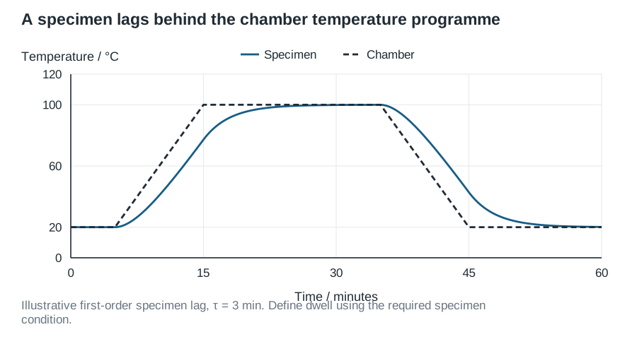
3. Build a defensible test sequence
First characterise electrical parameters and accessible thermal/mechanical indicators. Inspect representative initial assemblies. Instrument a suitable subset to verify that the prescribed specimen temperature history is actually achieved.
Run an initial block and examine the measured ramps, extrema and dwell. If the fixture causes unexpected gradients, correct the programme before interpreting accumulated cycles. Keep changes of fixture or profile visible in the record rather than treating the test as one unchanged exposure.
At defined checkpoints, perform matched-condition electrical checks and inspections. Functional failure, leakage drift, cracking and delamination are different observations; report them separately. Controlled mounting and inspection procedures reduce the risk of creating damage while handling specimens between blocks.
4. Interpret a degradation signal with supporting evidence
A higher thermal resistance can result from an internal attachment change or from an altered external interface. A cracked board solder joint can change electrical resistance without a change inside the semiconductor package. Establish the measurement boundary before attributing the change.
Imaging and destructive analysis can connect electrical or thermal drift to a physical location. The inspection method has its own resolution and detection limits. Absence of a visible defect is not proof that no damage exists.
An example fatigue form is
\[N_f=A(\Delta\varepsilon_{\mathrm{inel}})^{-m}. \tag{2}\]The inelastic strain range is generally obtained from a suitable material/structural model or calibrated relationship. Substituting chamber temperature excursion directly for strain requires additional assumptions. Parameters fitted for one joint geometry and mechanism may not transfer to a different package.
5. Keep this test distinct from power cycling
Passive cycling can heat much of the package together. Active self-heating can produce strong die-to-case gradients and different local fatigue. Infineon’s comparison of active and passive thermal cycling discusses their use for studying package attachment ageing; access to the full paper may require a vendor account.
Neither test alone proves complete application reliability. Select the tests from the actual mission profile and suspected mechanisms. A combined sequence can be useful, but its order may change the response and must be documented.
6. Report distributions and observation limits
For each specimen, retain completed cycles, inspection times, last passing observation, first failing observation and the failure classification. Survivors and interval-censored failures contribute information; they should not be omitted from the statistical record.
Report the population, lot coverage and confidence limits alongside a fitted lifetime distribution. A passing qualification sample only supports the specified programme. It does not justify an unqualified statement such as “this package lasts a given number of field years.” The mission-profile chapter explains the additional modelling and evidence needed for that calculation.